Quartus Warnings
Real C++ programmers ignore warnings!
I received a Google Code Jam 2022 T-shirt:
NVIDIA created a ramen shop using the NVIDIA omniverse platform. Here is a video of the ramen shop (original blog post):
This video is absolutely mind-blowing for me. Using NVIDIA’s graphics technology, human beings are able to replicate the real world in digital systems with an amazing amount of details. This capability is fueled by the growth of the gaming industry towards a more realistic and exciting gaming experience.
The “omniverse” capability would help many industries digitalize. They can use omniverse to create more advanced and complex models (compared to traditional CAD models) and do more simulations before making a physical prototype, which will transform the development process and help companies innovate faster. This is a step closer to a fully digitalized world.
This book is a very fun book about computer architecture, and I highly recommend this book! It describes some design concepts that are quite useful in the real world:
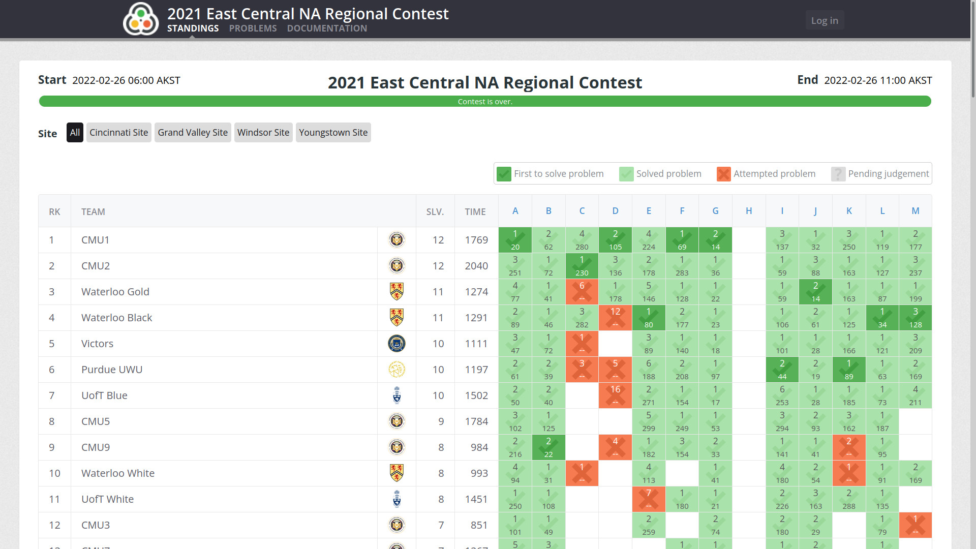
ACM-ICPC East Central North America Regional 2021 was held on Feb 27, 2022. Here is a link to the contest scoreboard, and I’m part of the team CMU9.
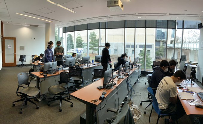
The contest was held on computer clusters on 5th floor of GHC, because the competition was remote this year. Here is a photo of the contest!
Notice the unusual 15 second time limit. We can brute-force with a simple $O(n^2)$ DP and costs $5 \times 10^9$ time. And surprisingly, it passed the time limit!
We want to select arbitrary two leaf nodes and the costs is all its ancestors. So for any two leaf nodes, we can compute their LCA and then compute their cost.
This problem looks too frustrating… I don’t like 3D objects.
If you plug in any curve to the equation of the corresponding line, you will find that each curve is a piece of another circle. Now you can calculate the circle area. You can add the area of sector in the circle (1), subtract the triangle from circle center to the endpoints (2), and add triangle from point O to the endpoints (3). Then you get the directional area and then sum up.
However, we got numerous Wrong Answer for this problem. There are two major issues. First, the line can intersect with the large circle. In this case, the generated circle has infinite radius and becomes a line, so you only need to calculate part (3). Second, when the circle sector is 180 degrees, you can’t determine whether it is $+180^\circ$ or $-180^\circ$. The two endpoints and the center of generated circle are on the same line. You will need to look at the sign of area (3) to determine the sign of (1).
This is a probability DP problem. You can use $f[i][j]$ to represent the probability of winning when you have i square remaining on your paper while there are j ball announces left. Now you can easily determine the probability of current ball announce eliminating a square, because the number of balls remaining decreases one when the number of ball announces decrease one. Then you can use Python bigint to avoid writing bigint manually!
This is a simuation problem. Every time when there exist circles to be merged, you simulate the merge operation. When there are no circles to be merged, you determine the next timestamp that a circle merge will happen, and fast forward to that time. Be careful of floating point precision problem!
Brute-force all possible prefixes. Because all integers are smaller than $2^{31}$, the length of integers are at most 10. So it will work.
(I don’t know how to solve this)
List the pinned elements and unpinned elements separately. First, in the optimal strategy, for any element, you operate on (pin/unpin) it at most twice. If you pin/unpin/pin element i, the result is equivalent to pin i at the timestamp of your last pin. If you pin/unpin/pin/unpin element j, the result is equivalent to pin/unpin j at the timestamp of last two operations (pin/unpin). Your previous operations to adjust the order become completely useless at the timestamp of your latest operation.
Now, for any element that begin in the pinned list and end in the unpinned list (or opposite), it can only be operated exactly once. For any element that begin and end in the same list, it can cost zero or two operations. We want to maximize the zero-operation element, so we can just greedily count how many elements do not need any operation.
Use a monotone stack to compute the nearest element larger than itself to the left and to the right. Then loop over all elements to find the answer.
First, we can construct a directed graph, with “u => v” denoting if v is stable, then u is stable (equivalently, any square of node u is one square above any square of node v). We have a “top” set (containing at most 2 elements) and a “bottom” set, and we want the minimum number of paths from all top nodes toward any bottom node, and paths can be shared. We can start by a BFS with sources from all bottom nodes.
If there are one top nodes, we just want a simple shortest path, and this is computed in BFS. If there are two top nodes, denoted by root1 and root2, an existing solution is the sum of distance from bottom node to root1 and root2. But the two top nodes can also share path to reach any bottom node. Then the path should look like a fork: whenever two path intersect, they intersect until bottom node. Now we can do another two BFS from root1 and root2, then iterate over all nodes (to consider it as the potential path intersection), and its value is the sum of three BFS (starting from i to root1, root2 and bottom node).
We can iterate over all possible directions, and for any square, count if it exists on its corresponding diagonal. Then compute the minimum answer among all direction.
In this problem, because you can only move left/right/down, and you can visit one square only once, we know that we always visit a continuous segment on any line. Now we can maintain a Trie of the input strings, and make sure we are always staying on some node on the Trie. We can use DP with state $f[i][j][k]$ to represent we are currently on the i-th line, j-th column and Trie node k. Then we attempt to walk on the (i + 1)-th line and starting from column j. Notice that if we are on a Trie terminal node, we have the option of going back to root and continuing, so we have to maintain an array of all possible current Trie node.
Icarus is a great theme for Hexo. And we can also customize it to make it more personal! We assume you installed hexo-theme-icarus as a node package via npm. If not, you can replace all the node_modules/hexo-theme-icarus
path below to corresponding installation path. And make a backup of your current configuration before you proceed in case of any error!
The various containers, or “cards”, on the web page already have rounded corners. However, sometimes they don’t look round enough. We can manually adjust how much we want the rectangle corner to be curved. Go to node_modules/hexo-theme-icarus/include/style/base.styl
and change $card-radius
to your preferred size. I’m using $card-radius ?= 16px
.
By default, the “primary” color of this website is blue, which is the color of the color of hyperlinks, and active elements when you hover your mouse. This can be customized in the same base.styl
file. Change the $primary
variable to your favourite color, and there’s also other interesting variables like $navbar-item-active-color
that you might consider to change.
In the same file, you can also configure other elements like card shadows. It follows the same format as the usual CSS box-shadow.
The default page width seems a bit too narrow under wide screens (there are some unused horizontal screen space). And you can modify it! Go to node_modules/hexo-theme-icarus/include/style/responsive.styl
and this Javascript code determines the page width. For the widescreen section under function fullhd, I changed it to max-width: $widescreen - 1 * $gap
and width: $widescreen - 1 * $gap
. It’s sufficient for me to just minus one multiply the gap. Thanks this blog for the solution!
This one seems fun. Instead of the default grey background, you can configure something more interesting. You can simply put the css inside hexo-theme-icarus. Go to this directory: node_modules/hexo-theme-icarus/source/css
, create a file (for example, bg.styl
. You can use the generic way of setting the background image of any webpage:
1 | body { |
Then, include this file to the Hexo generation system by adding
1 | @import 'bg' |
to style.styl
file. Now you have a working background image in your website! This blog uses a CG from Sakura no Uta as the background image.
The world has witnessed another unjust and evil war, even in the 21st century. We stand with Ukraine!
The game mentioned in the last post was completed! We demonstrated this game system in last week’s Build18 event from the ECE department (Project Haptic Rhythm Music Game). Here are some photos of the system:
The vibrating motors (the black discs in the photos) are fun! It provides a very powerful haptic effect as we attach it to a 5V power source and switched by a MOSFET from Raspberry PI GPIO ports.
And the code is structured so that it’s very easy to create customized games! You only need to create a “note” file containing the starting/ending timestamp and channel (1-4) for each block, and point the global constants in state.c to the new mp3 and note file.
tyz is currently developing a game based on OpenGL ES 3.0 for 3D graphics. This article will review how to develop an OpenGL ES 3 application.
There are two types of shaders: vertex shader and fragment shader. Vertex shader processes data for each vertex and both specifies the actual position in the “clip space” (gl_Position) and passes data to fragment shader. Based on the incoming data, fragment shader processes data for each fragment (similar to pixel, so fragment shaders are sometimes called pixel shaders) and specifies the color for the fragment. Both of shaders run on GPU to reduce CPU processing load.
This statement actually has a issue. Suppose you want to draw a triangle and the vertex shader passes on data about the three vertices. However, there are much more than three fragments inside the triangle surface that expects input. The graphics hardware will actually perform interpolation on the data from the output of vertex shader to input of fragment shader. Users can specify “flat interpolation” in OpenGL ES 3 API to disable such interpolation.
As users can write custom shaders, OpenGL ES 3 does not use a fixed graphics pipeline to perform different operations, like OpenGL ES 1.x. To support things like lighting effects, users should write vertex and fragment shaders.
Input data are passed to the shader programs through attributes and uniforms. Attributes can be different for different input vertices. You can input either an array or a single element and the corresponding data for each vertex will go to shader input. However, OpenGL ES 3 requires a minimum of 16 attributes for all implementations, so to make program runs on every platforms that conforms to OpenGL ES 3 specification, the user can use at most 16 attributes. Uniforms are the same for all vertices, and the minimum number of supporting uniforms are much larger.
Data transferring between main memory and graphics memory are expensive. It is not very efficient to transfer memory on each draw operation. OpenGL ES 3 supports creating a buffer on the graphics memory and storing data there, so that drawing is more efficient. Users can create a buffer by glGenBuffers and store by glBufferData. This is known as Vertex Buffer Objects. Because there are fixed number of buffer targets, users can use Vertex Array Objects to store multiple vertex array data, vertex indices data, etc. in different places.
Textures can be applied when drawing objects. You can create a texture by glGenTextures and input the bitmap data into the texture by glTexImage2D. Then you can access texture data in shader programs by a sampler2D uniform.
CMU Computer Club is hosting Demosplash 2021! There are a lot of exciting machines!